

SAFIERY UNIVERSITY
SOLAR PANEL TEST PROCESS
AND TEST REPORT FOR
TRIPPLE INSULATED SOLAR PANELS
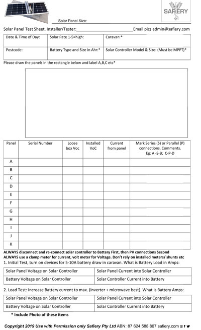
This technical article is designed to give value to the reader through more knowledge on Lightweight Flexible Solar Panels. Click on the image to download the test report.
 Principles of Testing
1. SOLAR PANEL DESIGN
The solar panel operates at optimum performance with MPPT solar controller.
The MPPT Solar Controller is vital to the performance of the solar panels. This controller takes the solar panel power (voltage and current) and converts it to the optimum mix to charge the battery. It effectively works as a battery charger and not a power supply. It takes about 15 minutes for most MPPT controllers to find the “maximum poer point”.
Solar panels can be combined in series so the positive of one panel feeds the negative of the second panel. You will then get a combined panel voltage of 48-52V in good sun.
It is wise to do parallel connections first and then a series connection. The reason being that is one panel drops out with a leaf or shade coverage, then the series connection set will drop in voltage and the optimizer will block this set out. If the panels are in parallel first and then in series, if one panel is out from leaves or shade, the system will contune at best performance.
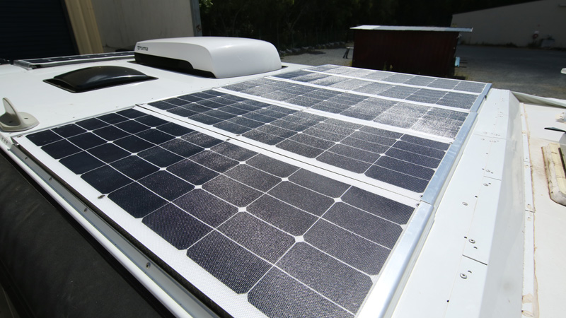
Draw the solar panels on the report and connect in parallel and/or series as it is wired up with simple connection lines. We suggest you do this right at the beginning of the installation to be sure as to how you plan to wire the panels.
2. SOLAR CONTROLLER
CHECK that the solar controller can accept a high panel voltage over 50V. Some well known brands like Enerdrive cant accept higher voltages. if you need to replace the solar controller, then EPever Tracer 30A or 40A is excellent BUT you have to program these for Lithium Batteries for best performance.
The best Solar controllers for Lithium Batteries have a “boost function”. This means that if it is late afternoon and the batteries are in “float charge” mode and then is cloud cover for 10-15 mins, upon return of the sun, the solar controller will go into a “boost mode” of bulk charge for a programed period of time. This gives the batteris a real boost in capacity before nightfall. the EPEver controller has this feature as do many others.
3. SOLAR PANEL TESTING
Voc is the open cicuit panel voltage. This varies based on the solar irradiance and the panel design. Taking this reading in the solar conditions in which you are ytesting, gives us a feel for the irradiance on the day. It also confirms all the panels are consistent and meet the quality checks.
After installation, reset the solar controller by disconnection both the battery connection (generally pull the fuse) and the Panel connection (they have been disconnected anyway). Always connect the battery to the solar controller first, wait a minute then connect the solar panel wires. This is to allow the microprocessor of the solar controller to boot up and establish the battery voltage.
Measure the panel voltage and the current for each of the solar panel cables coming to the solar controller. If they are joined in the roof or overhead cupboard, then measure this at that point and complete the report. This is a very important step. The current you are measuring is NOT the battery current from the solar controller but the panel to controller current. it will ALWAYS be less than the solar controller to battery current.
4. INITIAL SYSTEM TESTING
This is with all the panels connected. You need to know the battery voltage as if this is high, the charge acceptance rate may be low depending on the battery type. (specially trus for AGM, not so for Lithium). The solar controller should boot up and operate in “bulk charge” mode for about 90 mins or more if the battery State of Charge is low. This is the condition we want to test in. So it is important to get the controller in “bulk charge mode”. Turn on some loads to get 5-10A coming out of battery and then complete the recording of panel and battery voltage and current AT THE SOLAR CONTROLLER.
5. UNDER LOAD SYSTEM TESTING
This is with all the panels connected and the battery under maximum load. The best way to achieve this with Lithium batteries is to use the inverter if it is fitted and operate the microwave with a litre of water inside and set to boil. On most caravans, the current draw will be 110-140A. If the batteries are AGM, then set the microwave down to a lower setting and draw a max of 40A. The solar controller should still be in “bulk charge” mode so do this quickly after the first test. If it isnt, reset the solar controller by disconnecting the panel voltage and then the battery voltage as described before. Then complete the recording of panel and battery voltage and current AT THE SOLAR CONTROLLER.
6. CUSTOMER HANDOVER
Offer to step through the report with the customer. Have photographs of the current and voltage values if the customer is collecting at a later time and cant see the actual test results.
 Installation if buying an iKamper Kit from Drifta
These are ordered directly from Drifta who prepared and bond the kits specially for iKamper.
Keep the ends of the solar panel cabling dry and insulated while installing as they will have some voltage. It is best to do the installation under cover or in the shade. Before connecting the solar panels to the solar controller, cover the panels to reduce the solar output. The power from the panels in this state is very small and presents no danger to the DIY installer.
Drifta rout out the polycarbonate underneath to match the profile of the iKamper. You MUST specify the model as there are 2 profile shapes.
They ship the pre-assembled solar kit to you.
You (or your installer) would then place on iKamper as a dry fit to ensure the profile is good. If good then proceed to install on iKamper with just the Sikaflex252. Remember that weights are need to keep pressure on the Solar panel kits as the SikaFlex252 bonds for a 24 hour period.
Wait at least 48 hours after curing before travelling at speed.
Download the iKAMPER test Sheet by clicking on test sheet image: